Those Fabulous Clippers
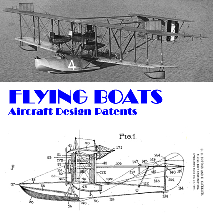
Design Patents for Flying Boats

Join Us on Facebook
Those Fabulous Flying Boats

Our treatment of aircraft began as an account of my trials and tribulations in building a 1948 airplane model kit. Since then, we have developed a wealth of patent diagrams for historic aircraft, so many in fact that the page was very slow in loading. On November 25, 2009 we split the material into six segments, corresponding to the six boxes or "buttons" below. If you came in from a search engine looking for something very specific, click here for the Analytical Index that will enable you to find a specific topic.


For those of you who don't like buttons, go to the analytical index to find just what you're looking for.
Hello! Welcome to our page about those fabulous Flying Boats. If you came here with a specific purpose, here are some helpful shortcuts
- Mythology and Reality of Flying Boats
- Flying Boats and Patents
- Curtiss NC-4 Round the World Flying Boat
- Consolidated P2Y Flying Boat
- Consolidated PBY Catalina Flying Boat
- De Seversky Proposed Transoceanic Clipper
- Martin Model 130 China Clipper Flying Boat
- Short-Mayo Composite Flying Boat
- Boeing B-314 Clipper Flying Boat
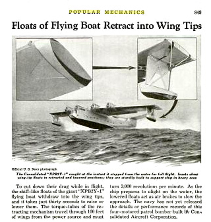
- Consolidated PB2Y Coronado Flying Boat
- Martin P5M Marlin Flying Boat
- Curtiss SOC Seagull Observation Floatplane
- Curtiss SO2C Seamew Observation Floatplane
This is part of a general Retro Lifestyle/Swing Dancing website. We have a Guide to 1940s Treasures and a Swing Dance Calendar for Washington DC.. Please feel free to Contact Us if you'd like to comment on the golden age of balsa wood models.
Mythology and Reality of Flying Boats
We were fortunate to obtain a large number of issues of Popular Mechanics during the period 1932-1939, the key points in the evolution of Trans-Atlantic and Trans-Pacific aviation.
Part One: Trans-Atlantic Aviation
This graphic show transatlantic aviation at the beginning of the 1930s:

Three Modes of Travel to Europe
Clipper to Brazil, Zeppelin to Europe, Steamship Home
From Popular Mechanics September, 1934
Click to Enlarge
As the 1930s began, aircraft simply did not have the endurance to brave the tricky weather and distances across the Atlantic. Lindbergh had shown that it was "possible" -- but a lone airman's highly risky flight did not add up to scheduled air service. Most heavier-than-air aircraft were flying boats. By 1934, commercial air transportation had begun between the US and the islands of the Caribbean. It was possible to fly from Miami to Rio De Janero in the Sikorsky flying boats made famous in the film Flying Down to Rio. At the same time, German zeppelins were plying a profitable trade transporting passengers from Rio to Dakar (the closest point between the Eastern and Western hemispheres) and thence to Europe. The stormy Atlantic was as yet impassible, so travelers returned on luxury steamships.
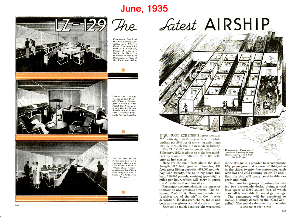
Dirgibles and Steamships
(left)Luxury Accommodations on the Hindenburg (June, 1935)
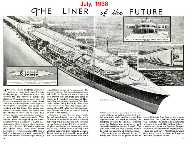
(right) Steamship developments in the 1930s (July, 1938)
Click to Enlarge
Our review has turned up a number of informative articles that will give you an in-depth understanding of the evolution of transatlantic air travel
A Look at Technical details of Transatlantic Travel
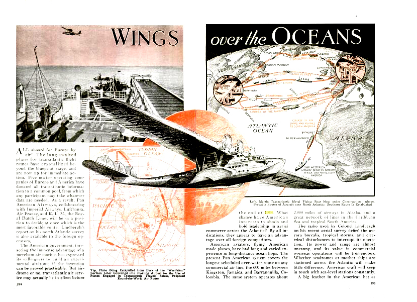
(left to right)Wings Over the Atlantic (March, 1934)
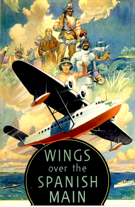
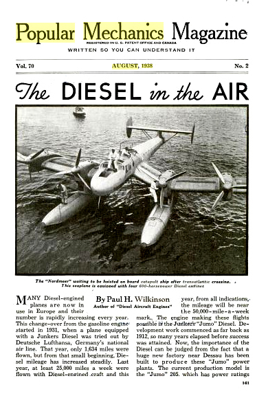
Wings Over the Spanish Main (November, 1935) Diesel in the Air (August, 1938)
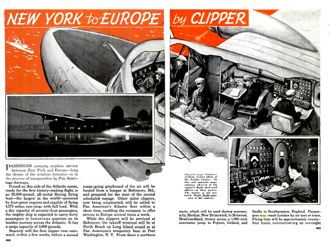
New York to Europe by Clipper
Click to Enlarge
Here are some articles that deal with luxury aboard some of the long-distance planes of the 1930s.

Luxurious Accommodations on Long Distance Planes
(left) Collection of Unusual Transatlantic Forecasts
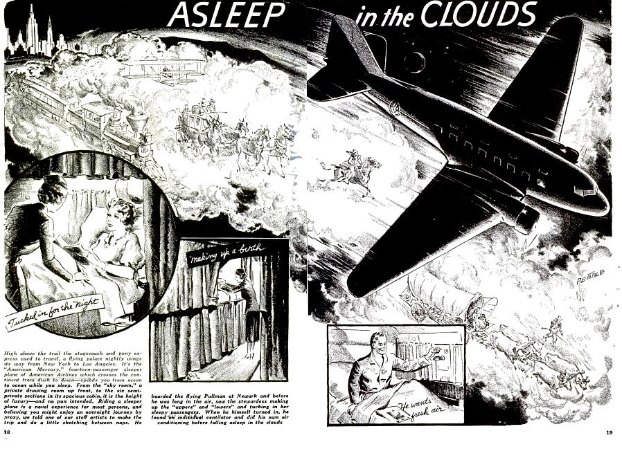
(middle) Asleep in the Clouds
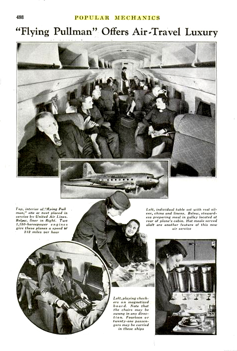
(right) Pullman of the Air
Click to Enlarge
Here are some wonderful color sections dealing with long distance travel

Special Color Inserts in Popular Mechanics
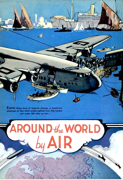
(left to right) Around the World by Air (Part 1)
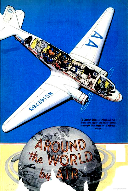
Around the World by Air (Part 2)
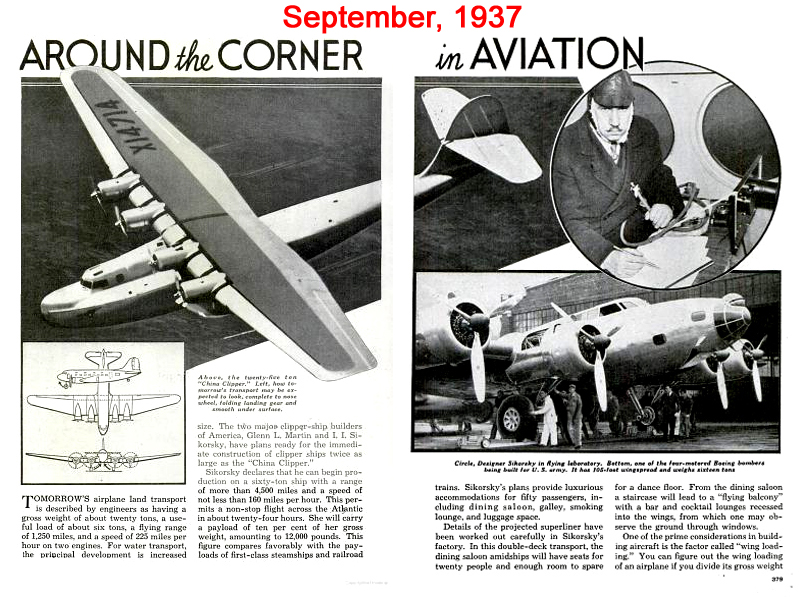
Around the Corner in Aviation
(right) Giant New Airliners
Click to Enlarge
For your reading pleasure, we have created ".pdf" files for these interesting articles. They contain a lot of photographs that are not often seen.
- Click Here to download "Luxury Accommodations on the Hindenburg"
- Click Here to download "Mid 1930s Developments in Steamships"
- Click Here to download "US to Europe By Air "
- Click Here to download "Wrong Way Corigan"
- Click Here to download "Wings Over the Atlantic"
- Click Here to download "Wings Over the Spanish Main"
- Click Here to download "Diesel in the Air"
- Click Here to download "New York to Europe by Clipper"
- Click Here to download "Collection of Unusual Transatlantic Forecasts"
- Click Here to download "Asleep in the Clouds"
- Click Here to download "Around the World by Air (Part 1)"
- Click Here to download "Around the World by Air (Part 2)"
- Click Here to download "Around the Corner in Aviation"
- Click Here to download "Giant New Airliners"
Part Two: Trans-Pacific Aviation
This graphic show Trans-Pacific aviation during the "Golden Age of Flying Boats":
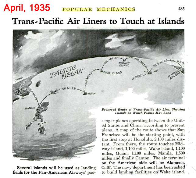
Island Hopping
Note the island stops...
... soon to become major WWII Battlegrounds
From Popular Mechanics April, 1935
Click to Enlarge
Distances in the Pacific are vast. Given the limited range of flying boats of the 1930s, it is fortunate that there were a number of island stops where planes could refuel and take refuge from hostile weather. The US was not the only country to recognize the value of strategically placed islands. Honolulu, Midway, Wake, Guam, and Luzon were all envied by the Japanese and were part of their plan of conquest. It cost many, many thousands of American lives to reclaim these islands.
Our review has turned up a number of informative articles that will give you an in-depth understanding of the evolution of Trans-Pacific air travel
Here are two articles that lay out the general structure of Trans-Pacific aviation and the very important role of weather forecasting. To give you some additional background on covering long distances with aircraft, we have also included a look at building a Trans_Canada airline.
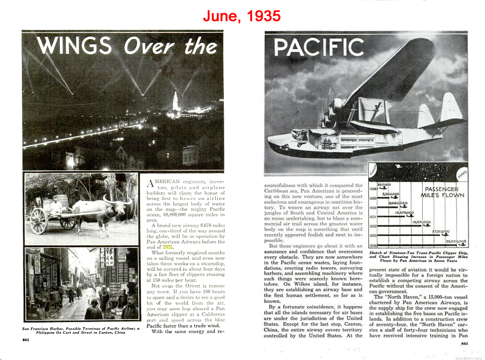
Fundamentals of Trans-Pacific Aviation
(left) Wings Over the Pacific (June, 1935)
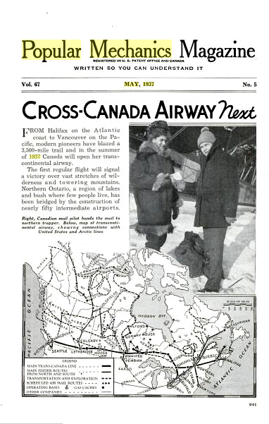
(Middle) Trans-Canada Airline (May, 1937)
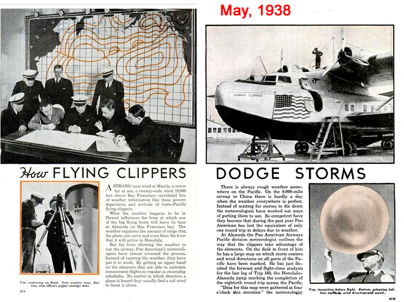
(right) How Flying Clippers Dodge Storms (May, 1938)
Click to Enlarge
The vast distances meant that planes had to be designed to carry a fairly large number of revenue passengers. The Pacific flying boats were called "Clippers" after the graceful old sailing ships of the tea trade. They were among the very largest airplanes and captured the attention of the public.

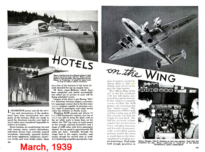
Size Mattered
(left)New Giants for the Airlines (February, 1938)
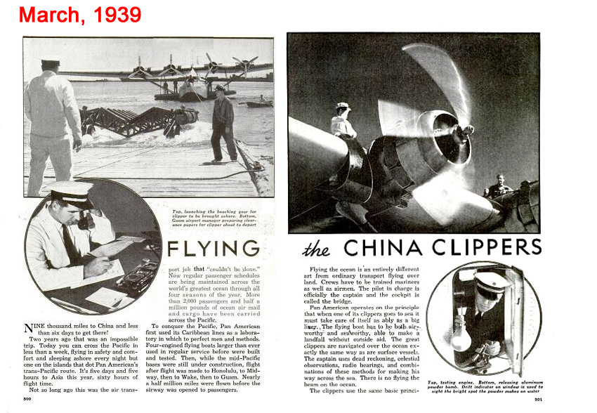
(middle) Hotels on the Wing (March, 1939)
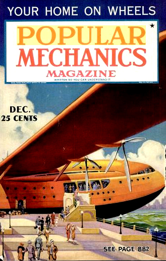
(right) Future Titans of the Skies (December, 1936)
Click to Enlarge
Our review turned up two articles about how new pilots were trained to meet the demands of Trans-Pacific aviation.
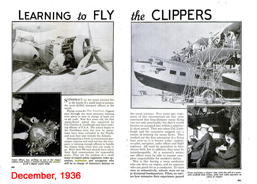
Flight Training
(left) Learning to Fly the Clippers (December, 1936)
(right) Flying the China Clippers (March, 1939)
Click to Enlarge
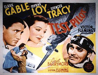
There was a fascination with Test Pilots -- brave young men who took unprecedented risks. These fellow were romanticized in films from Test Pilot (Clark Gable and Myrna Loy) to The Right Stuff. Eventually, the Test Pilot gave way to the Astronaut as a folk hero.

Romanticizing the Test Pilot
Click to Enlarge
Here are several articles from the 1930s about test Pilots.

Test Pilots
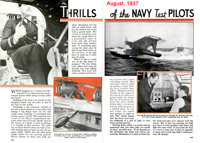
(left) Thrills of the Navy Test Pilots (August 1937)
(right) Test Flying the Sky Giants (May, 1939)
Click to Enlarge
For your reading pleasure, we have created ".pdf" files for these interesting articles. They contain a lot of photographs that are not often seen.
- Click Here to download "Wings Over the Pacific"
- Click Here to download "Building a Trans-Canada Airline"
- Click Here to download "How Clippers Dodge Storms"
- Click Here to download "New Giants for the Airlines"
- Click Here to download "Hotels on the Wing"
- Click Here to download "Future Titans of the Skies"
- Click Here to download "Learning to Fly the Clippers"
- Click Here to download "Flying the China Clippers"
- Click Here to download "Thrills of the Navy Test Pilots"
- Click Here to download "Test Flying the Sky Giants"
Flying Boats and Patents
A flying boat is a specialised form of aircraft that is designed to take off from and land on water, using its fuselage as a floating hull. Such aircraft are sometimes stabilised on water by underwing floats or by wing-like projections from the fuselage. Flying boats are distinguished from floatplanes because they use the fuselage to provide the main buoyancy of the aircraft.
Flying boats were some of the largest aircraft of the first half of the 20th century. Their ability to "land" on water allowed them to break free of the size constraints imposed by general lack of large, land-based runways, and also made them important for maritime patrol and air-sea rescue, capabilities put to great use in World War II. Following World War II, their use gradually tailed off, with many of the roles taken over by land aircraft types.
The flying boat was glamorized in the movies, especially in the Astaire-Rogers hit Flying Down to Rio. These planes provided luxury accommodations (including sleeping compartments) for the long journey to exotic places in the Orient.
In the 21st century, flying boats maintain a few niche uses, such as for dropping water on forest fires and for air transport around archipelagos.
Curtiss NC-4 "Atlantic Crossing" Flying Boat

Curtiss NC-4 "Atlantic Flying Boat"
Model Airplane News Cover Art for May, 1969
by Tom Wilbur, USN
Click to Enlarge
The NC-4 was a Curtiss NC flying boat, designed by Glenn Curtiss and manufactured by Curtiss Aeroplane and Motor Company. In May 1919 the NC-4 became the first aircraft to fly across the Atlantic Ocean, making the crossing as far as Lisbon in 19 days, with multiple stops along the way. The accomplishment was largely eclipsed in public memory by the first non-stop trans-Atlantic flight, lasting 15 h 57 min, made by British pilots Alcock and Whitten-Brown two weeks later.
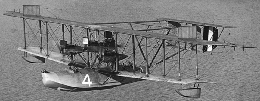
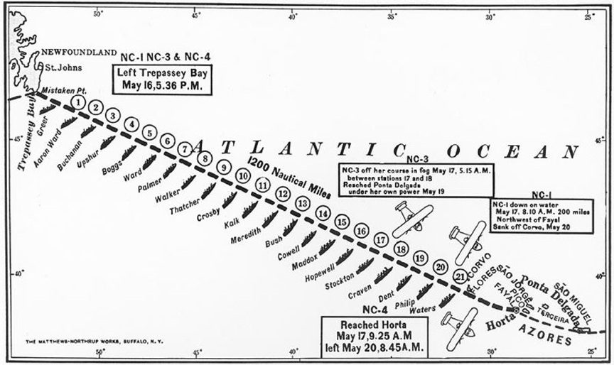
Curtiss NC-4 Flying Boat
Warships posted every 50 miles...
Click to Enlarge
The US Navy Transatlantic flying expedition began on May 8. The NC-4 was originally in the company of two other NC Flying Boats, the NC-1 and the NC-3 (NC-2 having been 'cannibalised' for spares to repair NC-1 before leaving New York). They left Naval Air Station Rockaway, New York, with intermediate stops in Cape Cod, Massachusetts, Chatham, Massachusetts and Halifax, Nova Scotia before reaching Trepassey, Newfoundland on May 15, 1919. Eight US Navy ships were stationed along the eastern seaboard to help the flying boats to navigate and to assist them if required.
On May 16 they left for the longest leg of their journey, to the Azores, with a further twenty-two US Navy warships stationed at 50 mile (80 km) intervals along the route. These 'station' ships were brightly illuminated, had their searchlights on and fired flares to help the crews to keep to the intended route. The NC-4 reached Horta in the Azores on the following afternoon, 1,200 miles and 15 hours 18 minutes later, having encountered thick fogbanks along the route; the NC-1 and the NC-3 were both forced to land at sea due to rough weather; the crew of the NC-1 was rescued by the Greek freighter Ionia, the NC-1 sinking three days later. the crew (including future Admiral Marc "Pete" MIscher) of the NC-3 managed to taxi their flying-boat to the Azores, where it was taken in tow by a US Navy warship.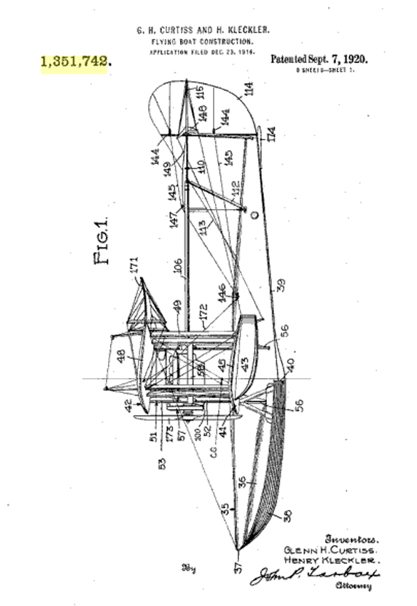
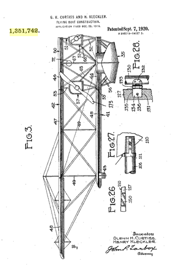
Curtiss NC-4 Technical Details
Patent No. 1,351,742
Click to Enlarge
Click Here for more information about the Curtiss NC-4 Flying Boat.
Consolidated P2Y Flying Boat
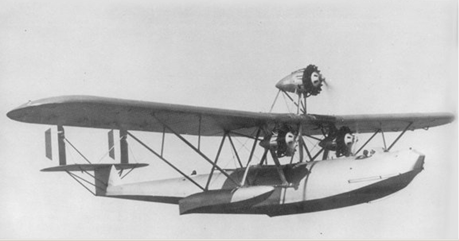
Captain Dick Richardson and Isaac M. 'Mac' Laddon, who were to occupy a significant place in the history of Flying Boats) designed a large parasol-wing flying boat for a Navy contract competition in 1928. Initially, the plane was powered by three engines. It was designated the "P1Y" and had the popular name "Admiral".
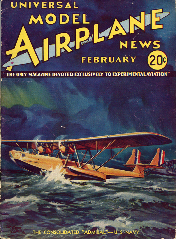
Consolidated P1Y1 "Admiral" Flying Boat
Model Airplane News Cover Art for February, 1934
by Jo Kotula
Click to Enlarge
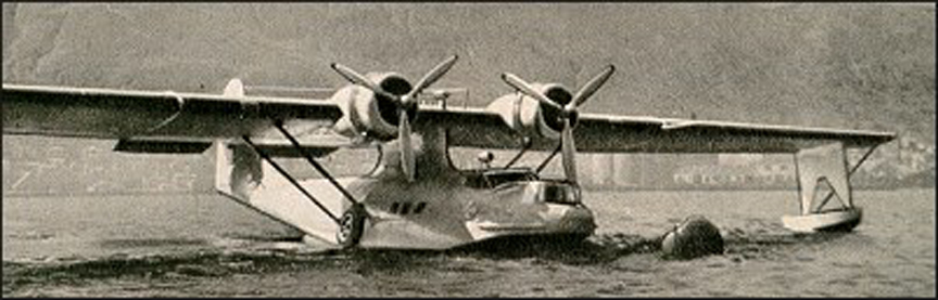
The first version had a single tail. With the availabilty of more powerful engines, the "Admiral" evolved into a two-engine airplane. A twin-tail was necessary to maintain appropriate controls. This aircraft, designated the P1Y2 was also called the "Admiral". The essential characteristics of this model are the open cockpit and un-cowled engines.
Real Plane
Click to Enlarge
The prototype made its first flight in 1929. Although Consolidated won the design contest, the production contract was opened to other bidders. This was a byproduct of standard naval procurement methods of the 1920s, whereby rights to a particular aircraft design became the property of the Navy and could ultimately be produced by any of its airframe contractors. based on cost considerations, the Navy Bureau of Aeronautics (BuAer) directed Martin to slightly reconfigure the design and ordered it into limited production in 1931-32 as the P3M, with three delivered as the P3M-1 and six as the P3M-2. The Glenn L. Martin Company submitted the low bid and was awarded the contract to construct the plane as the Martin P3M-1 and P3M-2.

Martin P3M
The low bidder....
Click to Enlarge
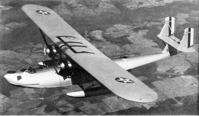
In 1931, the Navy conracted with Consolidated for an improved version, designated the Model 22 P2Y Ranger. It incorporated features such as an enclosed flight deck and cowlings on the motors. The Navy ordered 23 of these aircraft. The P3Ms operated alongside Consolidated's analogous P2Y production series, marking the beginning of a heated rivalry between Martin and Consolidated over various flying boat contracts during the 1930s.
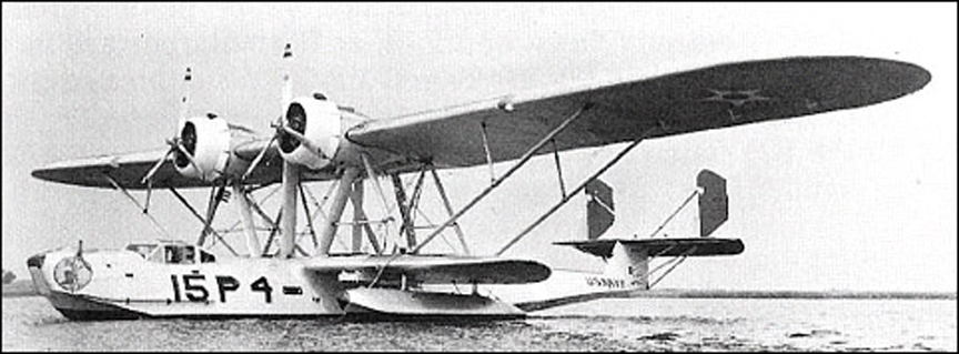
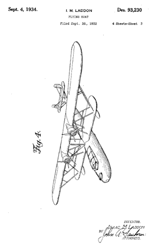
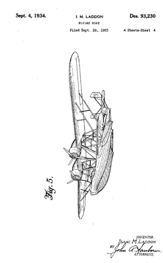
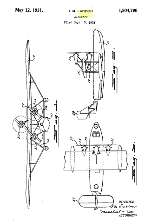
Patent Diagrams for the Consolidated P2Y Flying Boat
Design Patent D-93,230
Click to Enlarge
Click Here to learn how to get free patent diagrams
Click Here for more information about the Consolidated P1Y1 and P2Y Flying Boats.
Consolidated PBY "Catalina" Flying Boat
The Catalina was the most successful (and numerosu) flying boat in aviation history. It served extensively throughout World War II as a search and rescue plane, even (at times) delivering bombs. It began life as the Consolidated Model 28, designed by Isaac Laddon in late 1933.

Consolidated PBY "Catalina"
Model Airplane News Cover Art for April, 1944
by Jo Kotula
Click to Enlarge
The prototype first flew in 1935 and had distinctive features, most notably, the parasol wing with no supporting structures. This absence of struts and bracing wires offered an immediate improvement in performance. Another new feature was the introduction of stabilising floats which retracted in flight to form the wingtips. Initial trials of the prototype left little doubt that the Navy was about to acquire a significant aircraft. PBY-1 began to enter squadron service in 1937 and by mid-1938 14 squadrons were operational.
Consolidated PBY "Catalina" Flying Boat
Click to Enlarge
Initial export aircraft went to Russia, where the type was built subsequently in large numbers under the designation GST. The RAF acquired a single example for evaluation in 1939 and almost immediately ordered a batch of 50, the first of many to serve with Coastal Command. The name Catalina (adopted first by the RAF) was used later by the USN for the various versions which entered service. The type was also to serve with the RAAF, RCAF, RNZAF and the air arm of the Dutch East Indies. Many Catalinas remained in service for air-sea rescue for some years after the end of the war

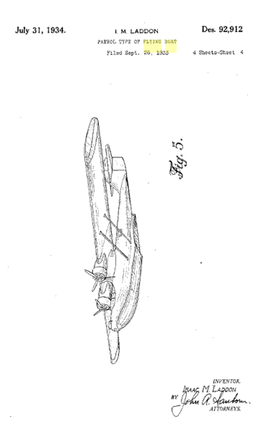
Patent Diagrams for the Consolidated PBY Catalina
Design Patent D-92,912
Click to Enlarge
Click Here to learn how to get free patent diagrams
The PBY was a very popular subject in the mass media from its unique retractable wing floats to its use in search and rescue. Here are three articles from the mid-1930s as found in our review of Popular Mechanics.
Consolidated PBY Catalina in the Media
(Left) June, 1939 (middle) May, 1937 (right) April, 1936
Click to Enlarge
Here is a video that has a "walk around" and takeoff of a restored PBY:
Click Here for more information about the Consolidated PBY "Catalina" Flying Boat.
DeSeversky Proposed Transoceanic Clipper
Jo Kotula was famous for selecting airplanes that were photogenic for the cover of Model Airplane News. On many occasions, they proved to be fabulous flops. This is the only instance that I can find where Kotula illustrated something that didn't exist, a fantastic transatlantic clipper design.
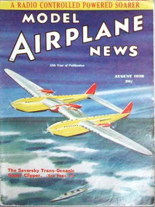
Seversky Transoceanic Clipper
Model Airplane News Cover Art for August,1938
by Jo Kotula
Click to Enlarge
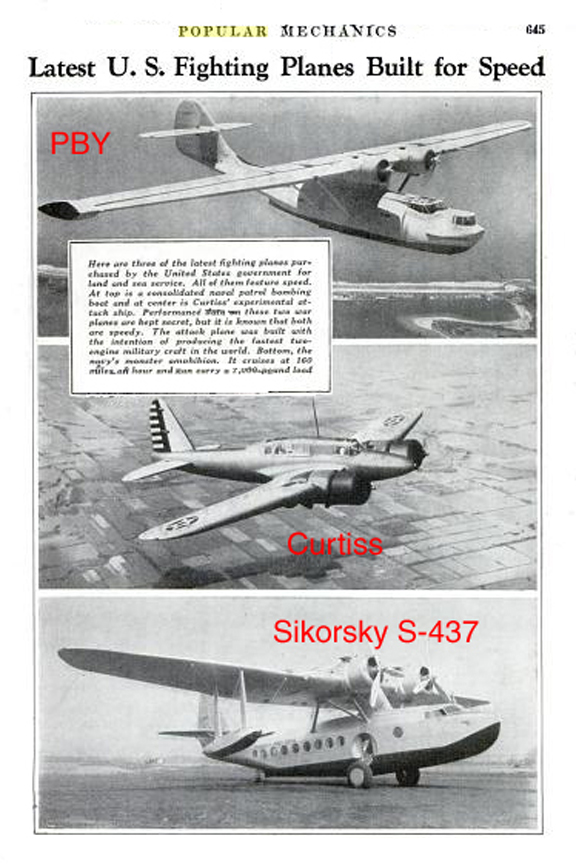
Flamboyant designer Alexander De Seversky had some success with a series of small flying boats, culminating in a four-engine airplane that was intended for Trans-Pacific flights, as shown in these photos from Popular Mechanics in 1935.
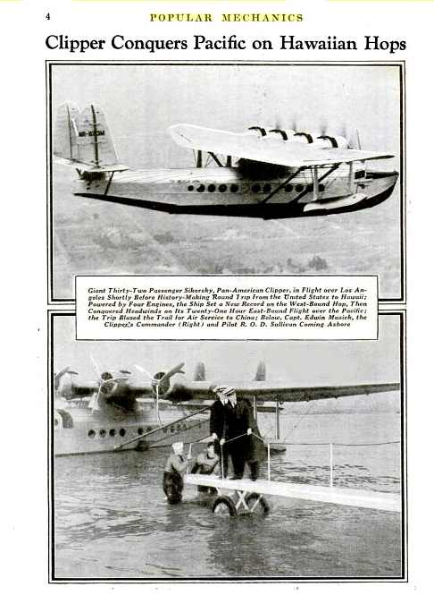
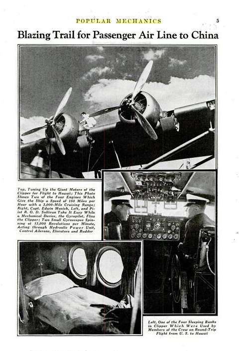
Seversky Pacific Clipper
From Popular Mechanics July, 1935
Click to Enlarge
Severskyproposed a fantastic trans-oceanic super clipper in response to Pan American Airways invitation for bids for a Transatlantic aircraft capable of a 5000 mi range, payload of 25,000 lbs, and 200 mph cruise speed. At this time, Pan Am was about to take delivery on the Boeing 314 boats which were just being built. The Seversky proposal was a gigantic 8 engine monstrosity. As shown in the patent diagrams and cover of Model Airplane News, it looked like a gigantic P-38 with a wingspan of 250 feet. The two booms have installed at their forward end two 2000 hp Allison engines geared to drive a single prop, one on each boom. These booms would also accommodate a number of passengers. The booms end in twin fins and rudders and are connected by a stabilizer-elevator.
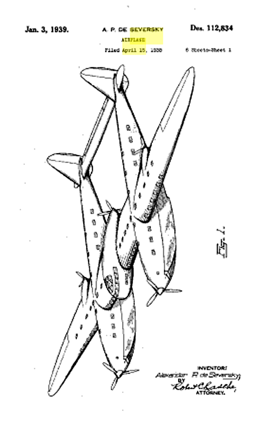
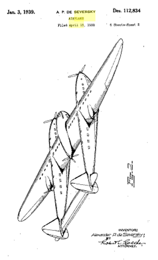
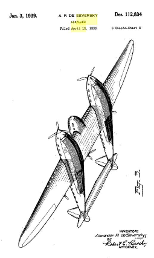
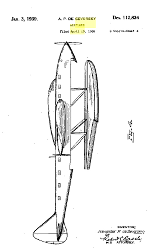
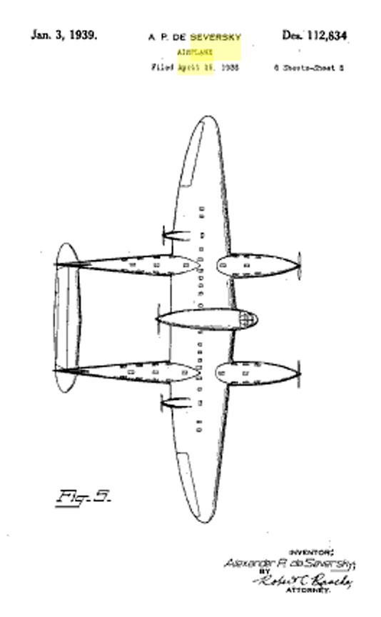
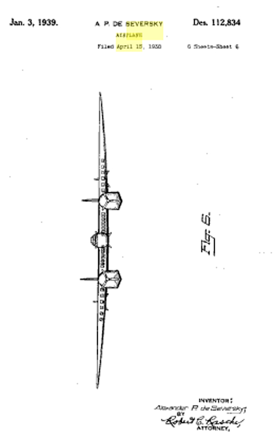
Seversky Transoceanic Clipper Design Patent D-112,834
Click here to download this design patent in its entirety
Click to Enlarge
The center nacelle would contain the flight deck and crew quarters. The rear of the nacelle would mount two more Allisons again geared to drive a single pusher prop. The wing section between the booms would contain more passenger accommodations and staterooms. The outboard wing sections would carry more passengers and also mount two more 2000 hp Allisons each driving a pusher prop, for a total of eight engines. Mounted on the bottom of the twin booms are two immense floats, which are retractable into the bottom of the booms operated by a hydraulic system. The floats also provide space for cargo.
Projected Performance Figures:
- Top speed: 300 mph
- Cruise: 200 mph
- Range: 5000 mi.
- Payload: 43,000 lb.
- Fuel Cap: 17,000 gal.
- Passengers: 200
- Crew: 16
Apparently, Seversky was quite serious about this thing, claiming that 174 engineers were assigned to do a design study. The only contemporary record of the proposed clipper is a photograph showing Seversky with a scale model of the aircraft. That, and the patent diagrams -- he put at least enough people on the job to get a design patent. While researching this, we found an article that appeared in the Pittsburgh Post Gazette on July 25, 1942 in which Col. de Seversky discusses his views on air power.
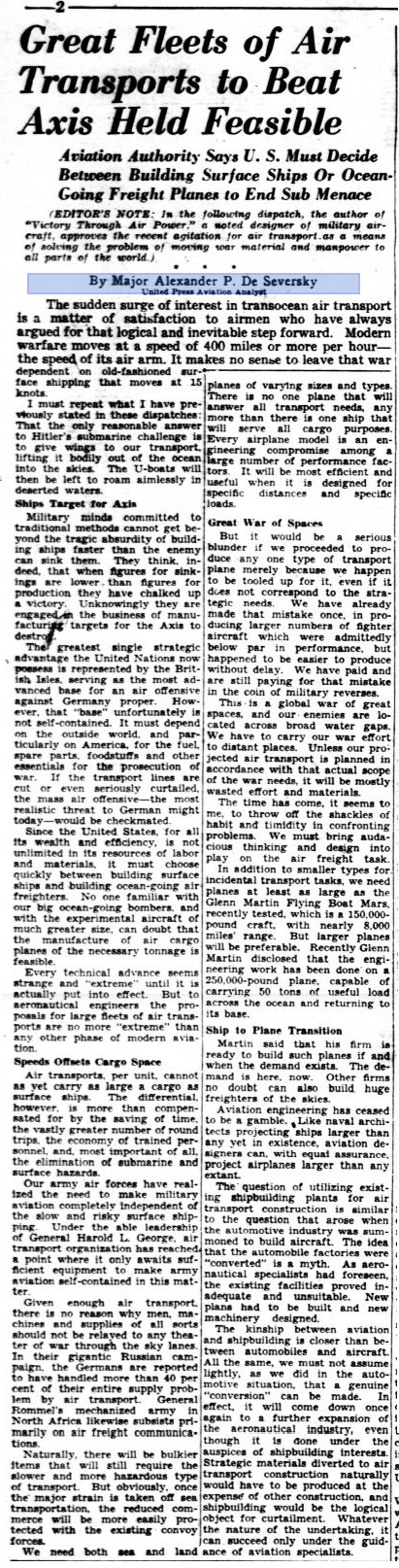
Article on Air Power by Col. De Seversky
Pittsburgh Post-Gazette July 25, 1942
Click to Enlarge
Walt Disney took him seriously enough to produce an animated feature called Victory Through Air Power, which you may watch by clicking the link. Col. De Seversky appears in the film.
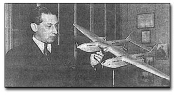
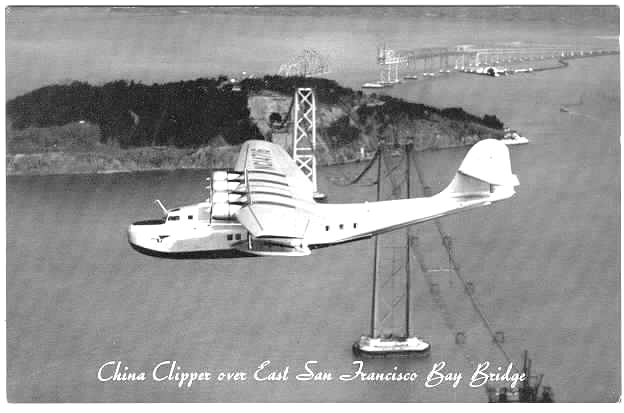
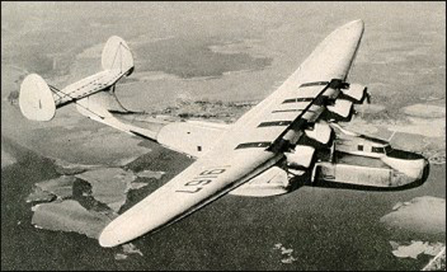
Martin Model 130 "China Clipper" Flying Boat
The Martin 130 was a large four-engined monoplane flying-boat designed for transoceanic services. Three were built for Pan American Airways in 1935 and on 21 October 1936 began operating over the Pacific from San Francisco to Manilla, Philippine Islands. Two were requisitioned by the US Navy in 1942. It had a twin-tail sister, as our reader Jamie explains:
"... The M-156 (twin-tail) was a follow on aircraft built for the next Pan Am flying boat contract. Martin lost the contract to Boeing and the marvelous B-314. The twin tail M-156 was sold to the Soviet Union where it saw many years of Aeroflot service . The Russians called it the Martin Ocean Transport, Martin's original name, and bristled at the more Western name, The Russian Clipper. The Soviets hated Juan Trippe for the capitalist he was..."
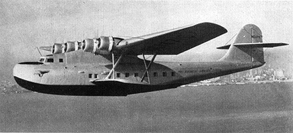
Martin Model 130 "China Clipper"
Martin Model 156 "Russia Clipper"
Check out Jamie's Website
Click to Enlarge
The hull was of advanced design and the result of exhaustive testing of models. Lateral buoyancy was provided by stub wings or 'seawings' instead of the conventional sponsons or outboard stabilising floats. Accommodation was provided for a crew of four and 36-48 daytime passengers or 18 sleeping bunks for night flying.
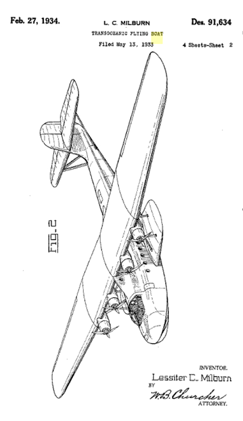
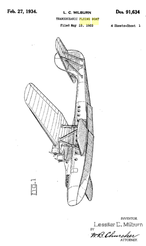
Patent Diagrams for the Martin "China Clipper"
Design Patent D-91,634
Click to Enlarge
Click Here to learn how to get free patent diagrams
Here is a video of the China Clipper as it arrives in Manilla on ts first flight:
In the May 10, 1937 issue, LIFE Magazine published a biographical story on Glenn Martin that includes some contemporary accounts of the China Clipper. Click here to download a ".pdf" of this article. Click Here for more information about the Martin China Clipper .
Short-Mayo Maia - Mercury Composite
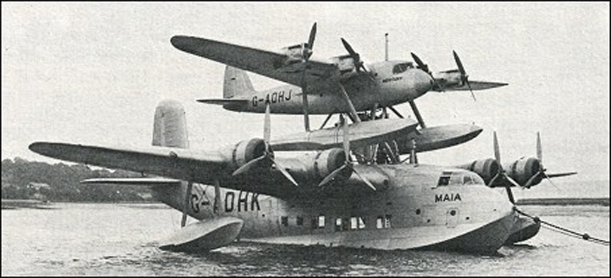
The Short-Mayo Composite
This really dazzled the public in 1938
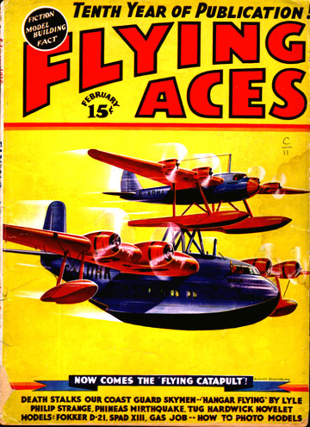
The Pulp Magazines had a field day (e.g. Feb 1938 issue of Flying Aces)
There is actually a video of this!
Click to Enlarge
The Short Mayo Composite was a piggy-back long-range seaplane/flying boat combination produced by Short Brothers to provide a reliable long-range air transport service to the United States and the far reaches of the British Empire and the Commonwealth. Short Brothers had built flying boats which were capable of operating long range routes across the British Empire but could only attempt the trans-Atlantic route by replacing passenger and mail-carrying space with extra fuel. It was known that aircraft could maintain flight with a greater load or for a longer distance if it did not have to expend energy on takeoff. Thus, Major Robert H. Mayo, Technical General Manager at Imperial Airways (and later a designer at Shorts) proposed mounting a small, long-range seaplane on top of a larger carrier aircraft, using the combined power of both to bring the smaller aircraft to operational height, at which time the two aircraft would separate, the carrier aircraft returning to base while the other flew on to its destination. We were fortunate to find an article in Popular Mechanics that described how this was actually done (with illustrations):
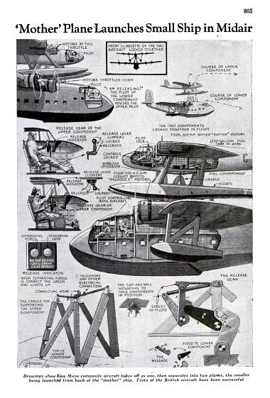
Technology of the he Short-Mayo Composite
... in Popular Mechanics November, 1937>BR> Click here to download a ".pdf" of the entire article
Click to Enlarge
The Short-Mayo composite project comprised the Short S.21 Maia, a modified S.23 C class flying-boat, and the Short S.20 Mercury seaplane, the latter attached to a pylon mounted on top of the fuselage of the former. This is almost impossible to describe in words. Fortunately, through the magic of YouTube, the actual newsreel accounts of this unusual experiment are available. In the main, the experiment was very successful given the state of aviation in 1938.
Without further ado, here is the actual newsreel footage
Click here to learn more about the Short-Mayo composite experiment.
Boeing B-314 Clipper Flying Boat
In 1935,Pan American Airways asked Boeing to design a new airplane for the lucrative transatlantic route. Boeing's designers based their work on the XB-15 heavy bomber, adapting the wing and horizontal tail surfaces to a flying-boat that could accommodate 74 passengers.
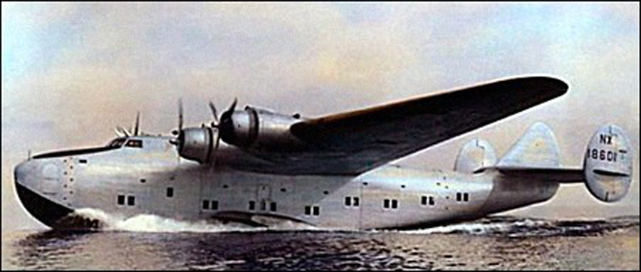
Boeing B-314 Clipper
Click to Enlarge
The first Boeing 314 flew in 1939. The plane began with a single fin and rudder (as shown in the patent diagram) but directional stability requirements led to the eventual triple-tail design shown in the publicity photo above and in the historical video, below:
In addition to Pan Am, BOAC also flew the Boeing 314. A total of seven of these airplanes were built.
.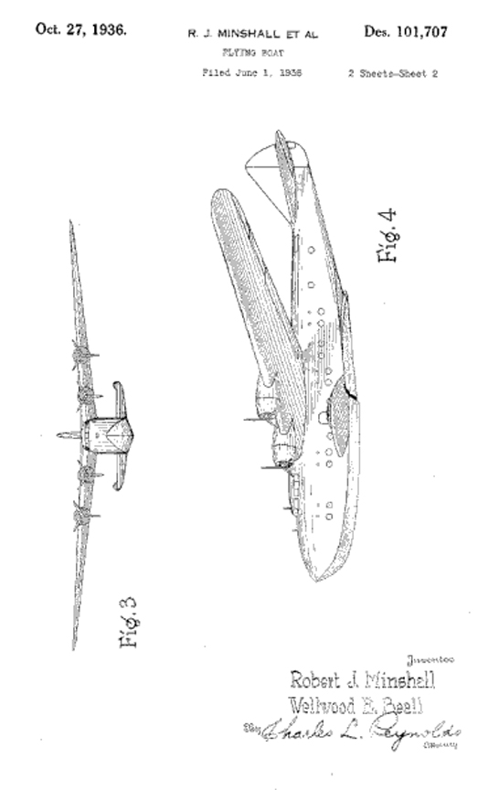
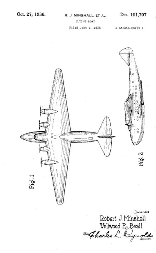
Patent Diagrams for the Boeing B-314 Clipper
Design Patent D-101,707
Click to Enlarge
Click Here to learn how to get free patent diagrams
Click Here for more information about the Boeing B-314 Clipper.
Consolidated PB2Y "Coronado" Flying Boat
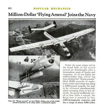
The prototype of the Coronado was delivered to the Navy in 1938. After service trials it served as Flagship of Aircraft, Scouting Force, The first production models went into service in 1941and remained in production until 1944 as a long-range patrol-bomber flying-boat
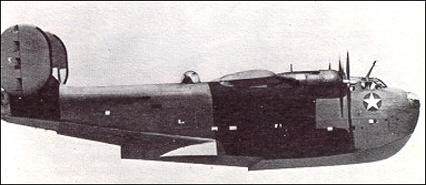
Consolidated PB2Y "Coronado"
(right) From Popular Mechanics,December, 1938
Click to Enlarge
Many Coronado flying-boats were converted into transports to carry 44 passengers; 3,000 lb of cargo; or 24 passengers and 1,9800 lb. of cargo. A naval ambulance version of the Coronado was also produced accommodating 25 stretchers. A total of 210 PB2Y-3 were built, ten of which were acquired by RAF Transport Command for transatlantic freight carrying
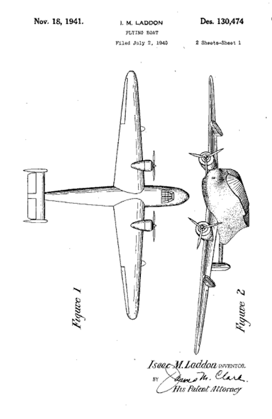
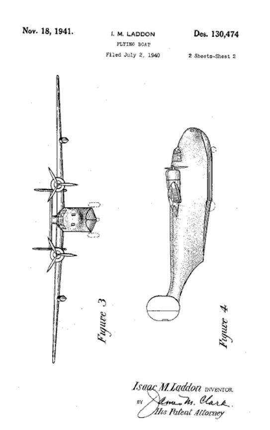
Patent Diagrams for the Consolidated PB2Y Coronado
Design Patent D-130,474
Click to Enlarge
Click Here to learn how to get free patent diagrams
Here is a video of the Coronado in action:
Click Here for more information about the Consolidated PB2Y "Coronado".
Martin P5M "Marlin" Flying Boat
The Mariner evolved from the successful PBM Mariner,combining the wing and upper hull of the Mariner with alower hull structure.
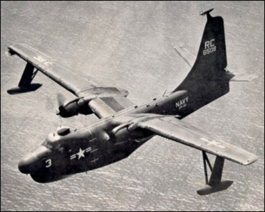
Martin P5M "Marlin"
Click to Enlarge
The modified hull incorporated radar-directed nose and tail turrets, as well as a power-operated dorsal turret. This prototype flew in 1948, but the P5M-1 was not ordered into production until 1950, and the type remained in service until the mid-1960s.
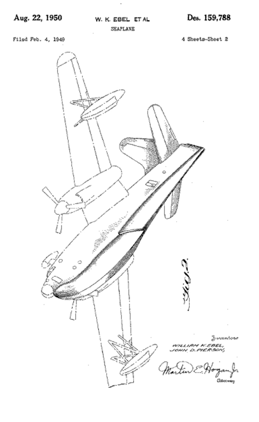
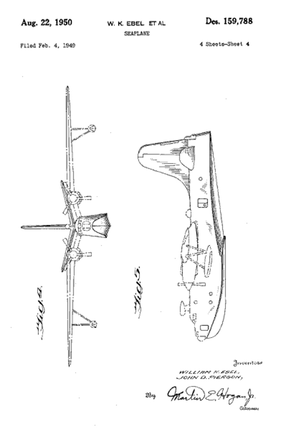
Patent Diagrams for the Martin P5M "Marlin"
Design Patent D-159,788
Click to Enlarge
Click Here to learn how to get free patent diagrams
Here is a video showing lots of views of the Marlin:
Click Here for more information about the Martin P5M "Marlin".
Curtiss SOC "Seagull" Observation Floatplane
The Curtiss SOC Seagull was a United States single-engined scout observation biplane aircraft designed by Alexander Solla of the Curtiss-Wright Corporation for the United States Navy. The aircraft served on battleships and cruisers in a seaplane configuration, being launched by catapult and recovered from a sea landing. The wings folded back against the fuselage for storage aboard ship. When based ashore the single float was replaced by fixed wheeled landing gear.
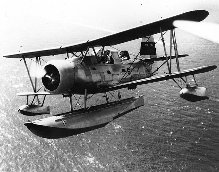
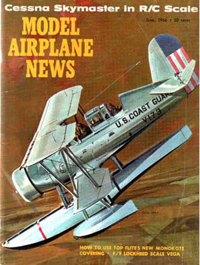
Curtiss SOC "Seagull"
Observation Floatplane
right: June 1964 Cover of Model Airplane News, drawing by Jo Kotula
Click to Enlarge
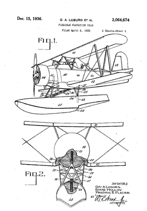
Curtiss "Seagull" Patented Float Gear
Patent No. 2,064,674
Click to Enlarge
By 1941, most battleships had transitioned to the Vought OS2U Kingfisher and cruisers were expected to replace their aging SOCs with the third generation SO3C Seamew (below). However, the SO3C suffered from a weak engine and plans to adopt it as a replacement were scrapped. The SOC, despite being a craft from an earlier generation, went on to credibly execute its missions of gunfire observation and limited range scouting missions.
When operating from ocean vessels, returning SOCs would land on the relatively smooth ocean surface created downstream of the vessel as it made a wide turn, after which the aircraft would be winched back onto deck. Here is a video showing the operation of a SOC from the Cruiser USS St. Louis:
Click Here for more information about the Curtiss SOC "Seagull" Observation Floatplane.
Curtiss SO3C "Seamew" Observation Floatplane
In 1937 the US Navy invited proposals for the design of a scout monoplane which would offer improved performance over the Curtiss SOC Seagull then in operational service. one requirement was that the plane had to be capable of operating from either ships at sea or land bases. This meant that easily interchangeable float/wheel landing gear was essential. The prototype had serious instability problems that were resolved by introducing upturned wingtips and increased tail surfaces. The amount of increased tail surface is shown clearly in the patent drawings below. The resulting aircraft was almost certainly the ugliest aircraft to be produced by the Curtiss company.
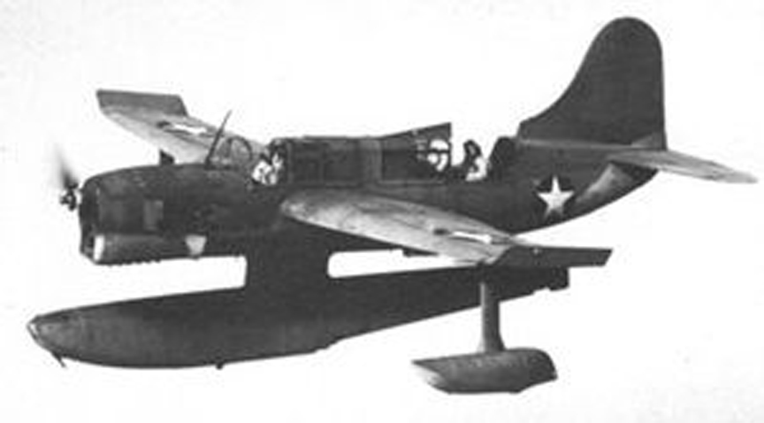
Curtiss SO2C "Seamew"
Click to Enlarge
The SO3C-1 entered service on board the USS Cleveland 1942; 300 were built before production switched to the SO3C-2 with equipment for carrier operations, including an arrester hook, plus an underfuselage rack on the landplane version to mount a 150 lb. bomb. The total production run of the latter plane was 456 of which 250 were allocated to the UK under Lend-Lease, In British service these aircraft were designated Seamew, a name adopted subsequently by the US Navy
The unsatisfactory performance of the SO3C-1 in the US Navy led to their withdrawal from first-line service. Many were converted for use as radio-controlled targets under the designation SO3C-1K, 30 being assigned to the UK, by whom they were designated Queen Seamew and used to supplement the fleet of de Havilland Queen Bee target aircraft.
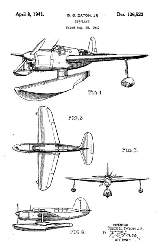
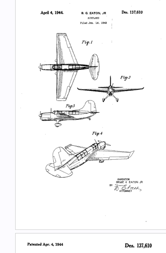
Patent Diagrams for the Curtiss SO2C "Seamew "
(left) Floatplane version, Design patent D-126,523
(right) Landplane version, Design Patent D-137,610
Click to Enlarge
Click Here to learn how to get free patent diagrams
Click Here for more information about the Curtiss SO2C "Seamew" .
Counter for the Entire Site (not just this page..)
Home | About Lindy | 1940s Collectibles | Upcoming Events | Vintage Clothing
The Guide - Establishments - Travel - Accessories
Music | Links | Photo Gallery | Extras | Contact